2M BEACON
VCO
I wanted to build a beacon for 2m from the ground up, it would be a good opportunity to learn something about PLLs, an interesting topic.
 |
I decided to try building my own VCO for 144 MHz, which I expected to be one of the more difficult aspects of this project based on my futile attempt to build a stable VFO for 10 m. However, "Introduction to Radio Frequency Design" by Wes Hayward W7ZOI contains a thorough analysis of the Colpitts oscillator and VCO considerations.
 |
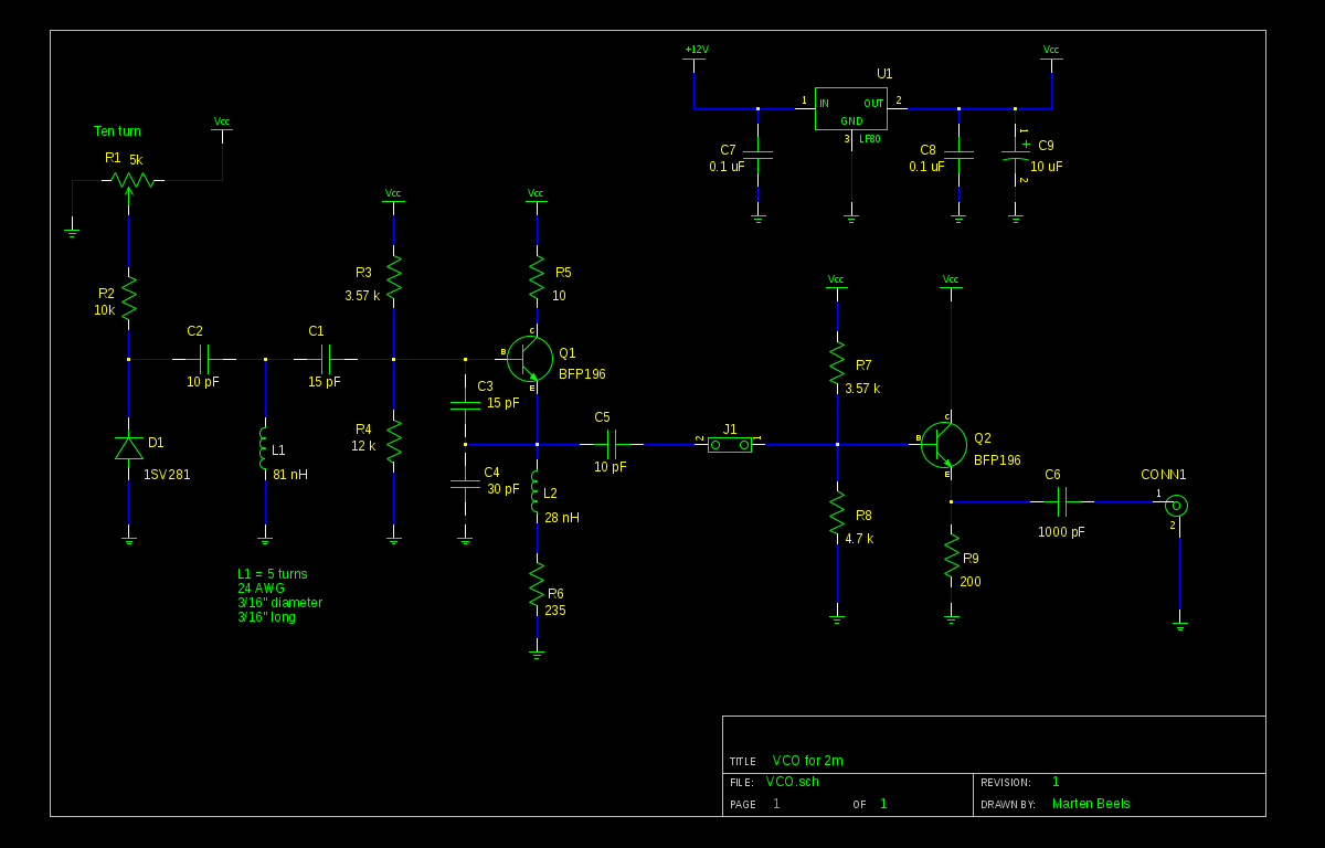
I put together the following circuit (see schematic below) and was somewhat shocked when it came up on 155 MHz, on the first try. I paralled a second 15 pF capacitor with C4 and got the tuning range to cover 137 MHz to 153 MHz over 8 volts, 2 MHz per volt.
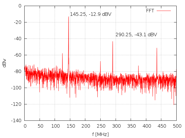 |
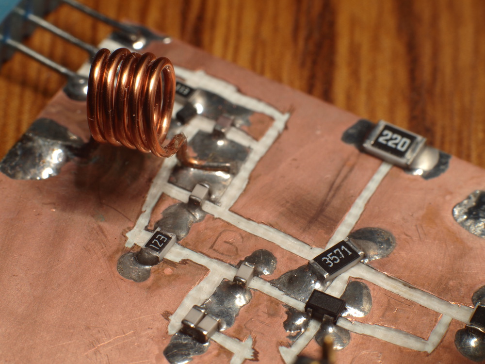
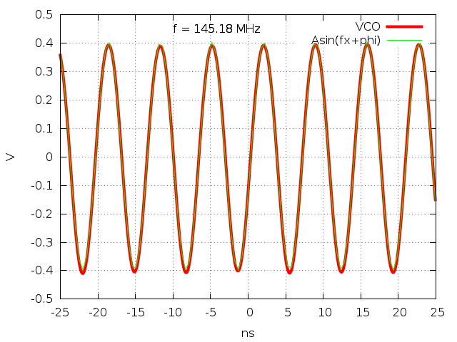
The output from the oscillator is very lightly coupled to an emitter follower by the capacitance of a pair of 0.10" pins. I had intended to be able to disconnect the buffer with a jumper, but found that there evidently enough coupling at 144 MHz to get good output without the jumper in place. The output looked cleaner, with less distortion. How much capacitance is there between those two pins, surely < 1 pF? The second harmonic voltage amplitude is down about 30 dB, quite acceptable.
 |
The varactor tuning diode is a 1SV281 which came in a smaller package than I expected, actually a bit smaller then 0603, but workable. You can just see it behind L1 in the top photo. The main "tank" inductor L1 is 5 turns of 24 AWG, 3/16" diameter, close wound which should be about 3/16" long. A roughly square (L = D) coil should have about the best Q. I could make several improvements to this circuit. Making C2 smaller would narrow the tuning range, and I could perhaps optimize C3 and C4, but it works well as is. I should make C5 smaller, perhaps just a few pF.
The transistor is a BFP196, often used in low noise amplifiers. The ft = 7.5 Ghz so it has plenty of gain at VHF (and most UHF) frequencies. I made no attempt to set the output impedance of the buffer to 50 ohms, its main function is to isolate the oscillator from fluctuations in the next stage.
 |
The next step is to determine the proper PLL control loop filter and choose an appropriate comparison frequency.
PLL Loop Filter
Working out the issues with the PLL loop filter took more time than getting the VCO oscillating, I had multiple issues that were confounding each other. I decided on a 100 kHz comparison frequency and started with a simple RC filter with a 3dB frequency at about 10 kHz. I'll spare the details, but here are some of my failed attempts.
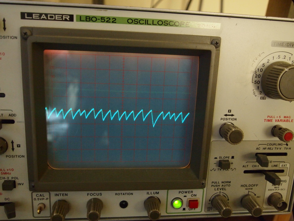
Loop oscillations:
 |
 |
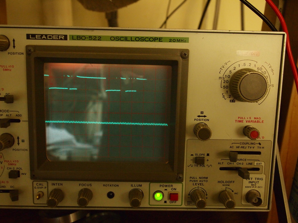
Loop oscillations with brief locks (top trace is digital locking signal, bottom trace is tuning voltage to VCO).
 |
 |
Apparently I was also getting strong coupling an undesirable feedback between my RF and reference signals. If I recall correctly, Dave from the EEVblog measured about 2 pF capacitance between two adjacent rows on a breadboard. At VHF frequencies this becomes a low enough impedance that the circuit will misbehave. I spent a bit more time being more careful and rerouting the reference and RF signals with RG-174 coax, avoiding the breadboard entirely.
 |
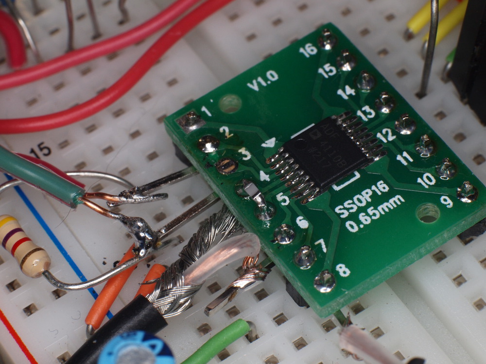 |
This mish-mash circuit has a mix of surface mount, through-hole, and RF. Note that the pins of the RF connections are bent up and out of the breadboard, keeping signals from getting contaminated.
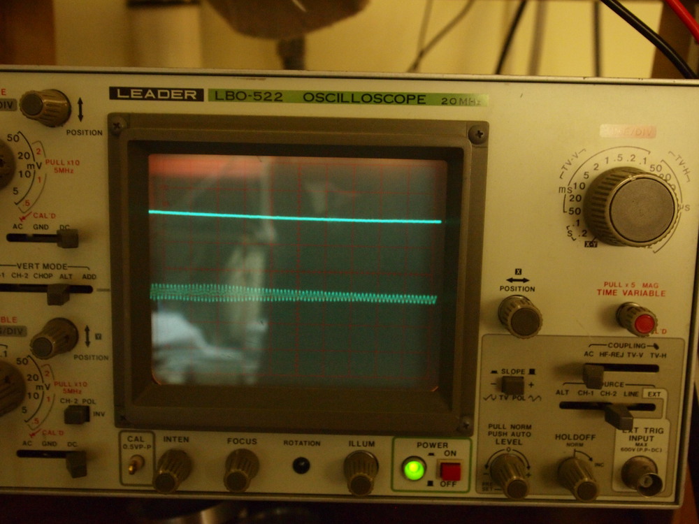
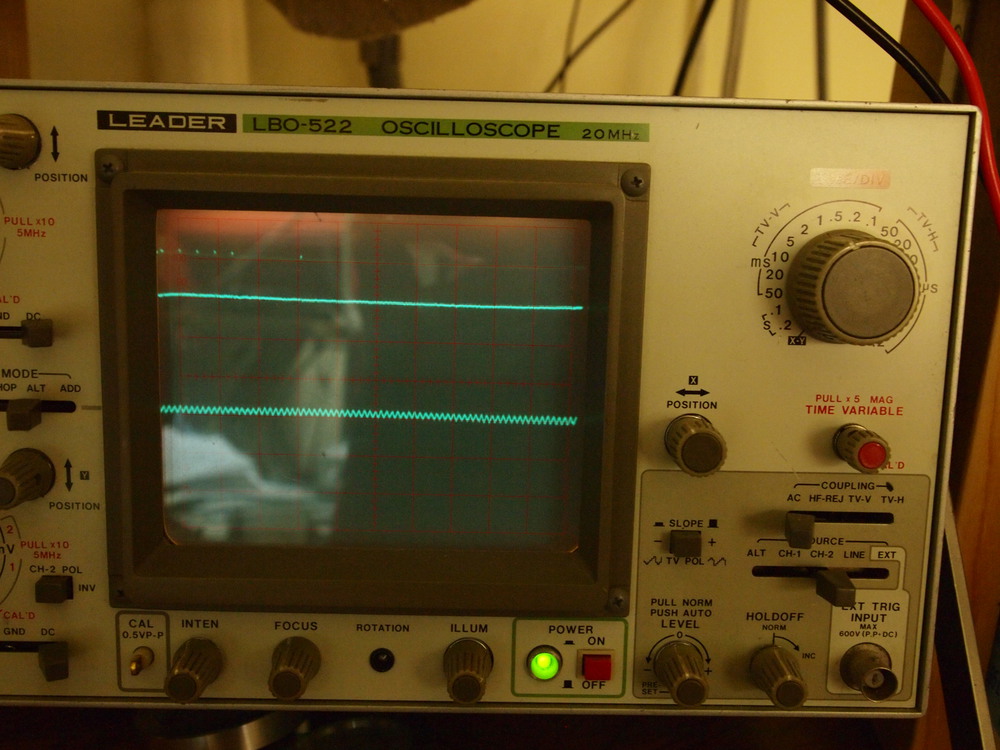
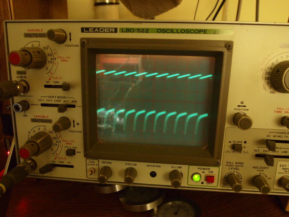
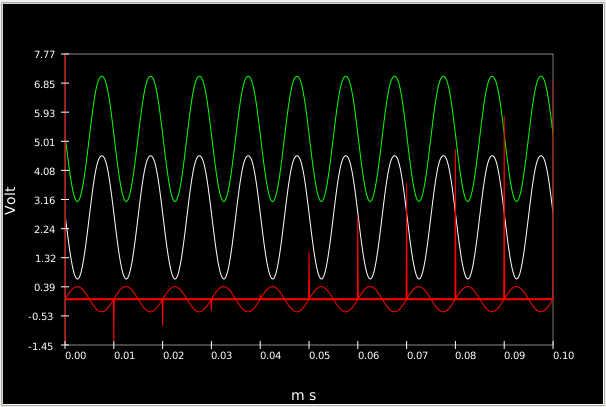
Then nearly success. I could hear a clear signal at my desired frequency, but also strong signals spaced evenly at 100 kHz intervals. It seemed that my loop bandwidth was too large, and my VCO was frequency modulated at my comparison frequency. Below is a plot of the analog loop detect signal (top) and tuning voltage to VCO (bottom), as well as Huw trying to explain to me that my filter bandwidth is TOO LARGE!
 |
 |
I also spent some time with the Analog Devices PLL design software, ADI SIM PLL. It is quite a comprehensive utility and was very useful. I ended with a PLL loop filter that looks like the figure below.
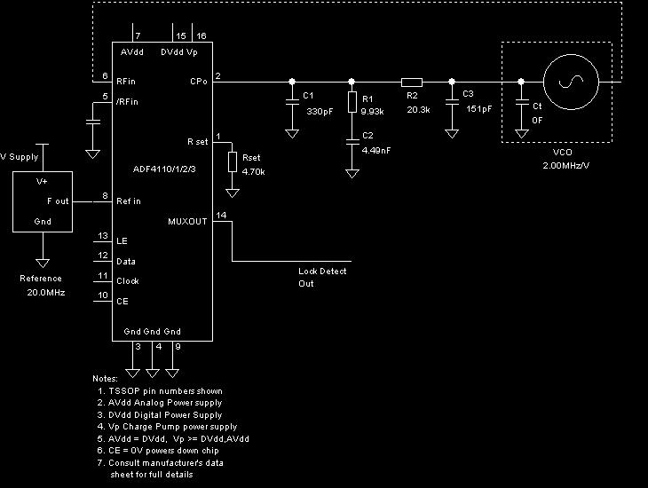
Now I have a very clean and stable signal, the reference spurs are low enough that I can just detect them with a 6" antenna in my FT-817 a foot or so away from the VCO. The output power is about -1 dBm.
RF Amplifier
Well, things had to get a bit worse before they could get better. My first attempt at an amplifier was a simple common collector + common emitter based on the same BFP196 (BJT) that I used in the oscillator and buffer. It got hot, attenuated the signal, and added distortion: quite a failure for an amplifier! Fortunately the design was ok, I just needed to tweak the DC bias point. I paralleled a 220 ohm resistor with the 100 ohm emitter resistor to get 68 ohms and then it worked much better.
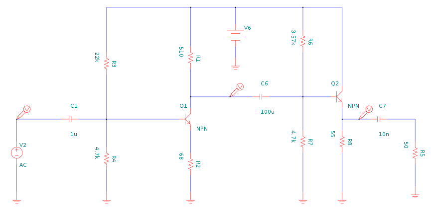 |
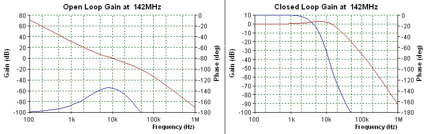
Click on the circuit for a larger schematic. The actual capacitor values are much smaller, on the order of a nF I think. This is not a proper VHF amp, but a simple broadband one that I could simulate, tolerant of BJT parameters, and I could test at low frequencies on my 20 MHz scope.
Even at 144 MHz, the simulation seems to match pretty well, see data further below. (Simulated at much lower frequency)
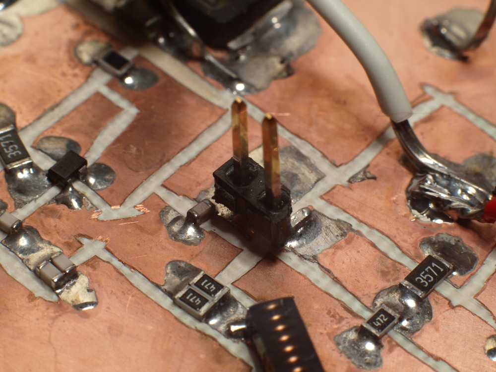
I'll spare the grody details, but after that point I ran into many issues and spent much time attempting various solutions. The main issue was inconsistent PLL locking, sometimes it would work if I put my thumb in the right place, touched a cable, or slightly moved things around. It would unlock if I tried to key the amplifier circuit. I added shielding, removed shielding, changed capacitor values, suspected my cheap SMA connectors, bad cables, and my layout. In the end, my biggest improvement came from changing the gimmick 0.10" header pin capacitor to a 61 ohm resistor. I suspect that my coupling was too light, and allowed feedback from the amplifier to destabilize things. It stills sometimes loses the PLL lock, so there is more work to do.
Keying Circuit
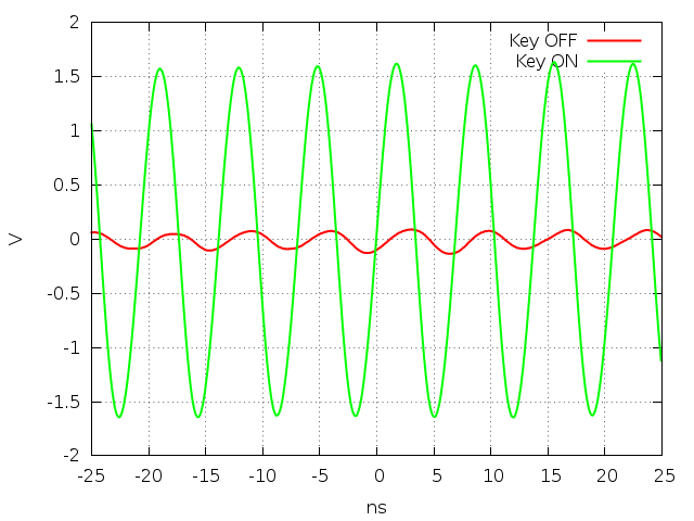
My first attempt at a keying circuit was to just turn on and off the supply voltage to the amplifier. However, this does not supply enough isolation, the oscillator still comes through with plenty of power. I will try a PIN diode switch next.
Output Impedance
In order to estimate the output impedance, I measured the peak-to-peak voltage open circuit, with a 50 ohm load, and with a 25 ohm load. The output voltage should follow Vout = Vs * RL/(RL + RS) where Vs is the open circuit voltage, RL is the load resistance, and RS is the source resistance. I can only determine the real part of the source impedance this way.
 |
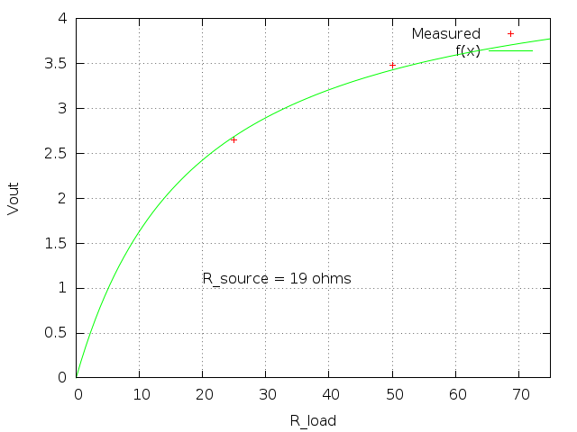 |
Using this info, I fit a source impedance of about 19 ohms.
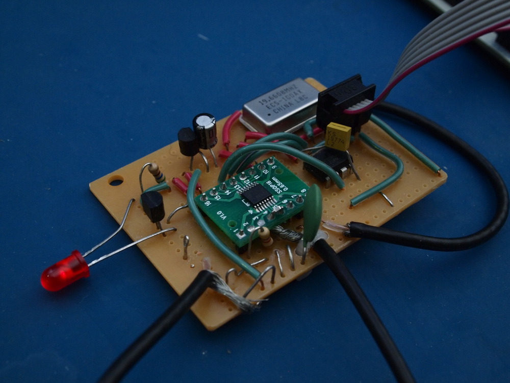
Putting it all together
At this point I have two crude boards assembled. The first has the VCO, buffer, and amplifier. The second has the PLL, reference clock, and MCU to load the PLL registers as well as key the amplfier to send CW.
 |
 |
The final steps will be to choose a frequency, build a suitable filter, get an antenna up, and try to get some on-air reports.
Output Filter
Choosing an L match should allow me to improve my impedance matching, and attenuate some of the higher harmonics.
Marten Beels 2015